University of Houston Capstone Team 6 - Blog 4
University of Houston Capstone Team 6 - Blog 4
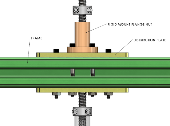
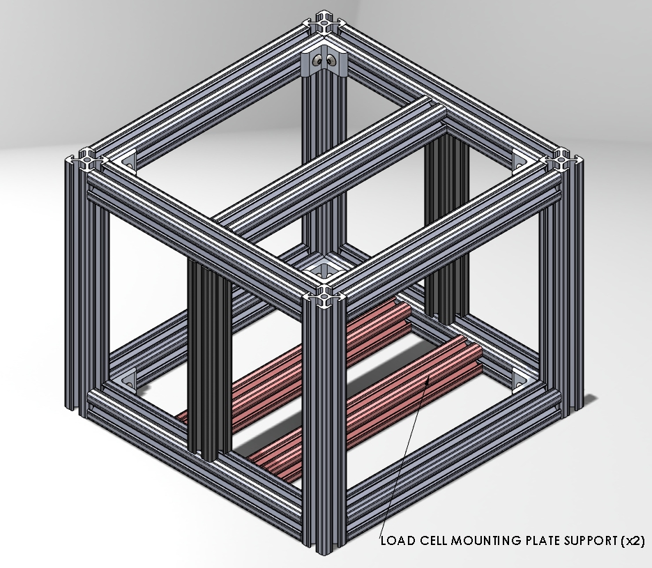
Team 6's final spring compression test device can withstand 500 pounds and a maximum temperature of 400 degrees Fahrenheit. In addition, the device is also capable of outputting line graphs of load versus time and load versus compression displacement through strain gauges, weights, finite element analysis, heat transfer analysis verified by thermocouples, and stress-strain analysis as a result of verification. In order to solve the main problems of large footprint, costly, difficult to install and unstable respectively, we fixed the whole device in a rectangular frame of 1ft x 1ft x 1ft and used mechanical operation instead of electrical operation to save money and also used flange nut and leading screw in cylindrical drums to stabilize the device.
Preparations that the team will have completed prior to the
start of the Spring 2024 semester include submitting a BOM to our client for
purchasing materials and parts for the assembly of the prototype. Similarly,
the team will also have drawings dimensioned and tolerance for all machined
parts that the prototype will require. These two tasks will allow the team to
have the majority of the parts ready to assemble and drawings will allow any
other parts to begin the process of machining.
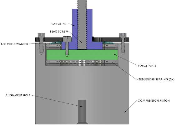
Some of the key analytical results from Team 6 that demonstrate the successes and strengths of the team's design are the simulation results, sizing, budget, and meeting the standard major constraints given by SLB. The team's meticulous attention to sizing is evident, ensuring that each component is optimized for performance. This is particularly exemplified in the incorporation of thrust bearings to counteract torsion, showcasing the team's strategic approach to address potential issues within the system.
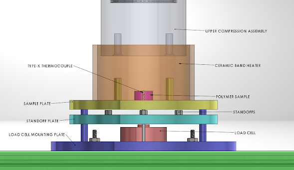
The budgetary considerations are another key factor in the analytical results, underscoring the team's ability to balance cost-effectiveness without compromising on quality. Meeting the standard major constraints set by SLB further attests to the team's ability to align their design with industry standards. Moreover, the strengths of the model extend beyond the theoretical framework to include practical features, such as a load cell tolerant of extreme conditions such as its capability to withstand temperatures of up to 400 Fahrenheit and support a force of 500lbf. The team's innovative solution for measuring the spring sample, involving a ceramic band heater reaching 900 degree Fahrenheit and a thermocouple k type for accurate temperature measurements, reflects a thorough consideration of real-world application challenges. Additionally, the protective measures for the load cell, incorporating a second plate spaced off with standoffs, demonstrate a commitment to durability and longevity in the system's functionality. Overall, Team 6's analytical results not only showcase the project's achievements but also provide a detailed understanding of the design's resilience and adaptability.


Comments
Post a Comment